Physical Address
304 North Cardinal St.
Dorchester Center, MA 02124
Physical Address
304 North Cardinal St.
Dorchester Center, MA 02124
→ Article about finding the pose (position + orientation) of an object relative to the camera using ArUco markers in OpenCV.
ArUco markers are specifically designed binary markers for pose estimation (position + orientation) of an object relative to the camera.
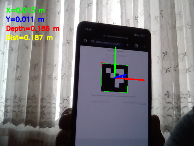
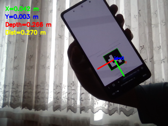
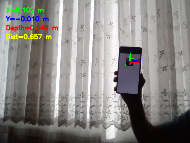
By using these markers, you can find the real-world coordinates of a marker, including depth. You can even think of these markers as a tool for creating a low-budget depth estimation system.
If you want to find a position of an object (it can be anything like clock, robot, etc.), you just need attach an ArUco marker to the object, and you can find all the information in any unit you want(meter, cm, mm).
In the last article, I showed you how to calibrate your camera with OpenCV, and in this article, I will use this calibration parameters and combine them with ArUco markers to measure depth using only one camera and one ArUco marker.

Before starting to play with these markers, you need to calibrate your camera. I am not going to explain the camera calibration process here because I have an article about it; you can read it. It takes about 5 minutes, and the process is the same for every camera.
After the calibration process, two different parameter sets are saved:
By using these two parameter sets, images will look more like what you see with your eyes rather than distorted images. Later in this article, before calculating the pose of an object with the solvePnP function, we will use these.

ArUco markers are basically binary images composed of black and white squares. There are different combinations, and OpenCV provides predefined dictionaries that contain markers in different combinations, such as:
cv2.aruco.DICT_4X4_50: 16 total bits(white and black pixels) with 50 unique combinations.cv2.aruco.DICT_5X5_100: 25 total bits with 100 unique combinations.cv2.aruco.DICT_6X6_250: 36 total bits with 250 unique combinations.
By using these markers together with the camera parameters and the premeasured marker size, you can find the markers’ real-world position (x, y, z) relative to the camera, and that is exactly what is this article about.

You only need few things, first you need to calibrate your camera and save calibration parameters. I saved my parameters in a YAML file, so I dont need to calibrate my camera every time. If you follow my article, you will see how to calibrate camera and save calibration parameters to a yaml file for later usage.

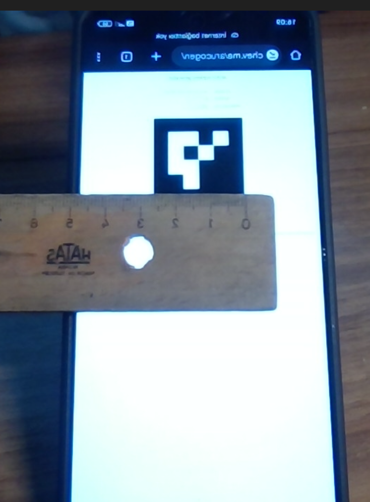
yaml file that contains calibration parametersAnother thing that you need is to print an ArUco marker. Actually, if you don’t have a printer this is not a problem. I found a marker on the internet and displayed it on my phone’s screen, and it worked perfectly. But the more common way is to download a marker and print it.
You can use this website to generate ArUco markers, but use the same dictionary in both the code and on the website. I will use the first option, which is 4X4.

The last thing you need is a ruler. By using the ruler, measure one side of the ArUco marker. Mine was 27 mm. If you are using a tablet or your phone, don’t zoom it, because once you measure this value, you can’t change the size of the marker; otherwise, the result will be wrong.
I explained all the code with comment lines; now I will explain the main flow and share the code.
First, an ArucoDetector instance is created. This will detect ArUco markers and return coordinates and marker IDs. Then, using the drawDetectedMarkers function, detected markers will be drawn on the frame.
Finally, with solvePnP function all the position and orientation information is calculated. As an input, solvePnP function expects:

Don’t forget to change:
calibration.yamlmarker_length
import cv2
import numpy as np
import yaml

# Load calibration data with Python's yaml
with open(r"calibration.yaml") as f:
    calib = yaml.safe_load(f)

"""
load your camera’s intrinsic matrix and distortion coefficients from a YAML file
- camera_matrix is the 3×3 intrinsic parameters matrix.
- dist_coeffs holds lens distortion parameters.
- marker_length is the side length of the ArUco marker in meters.
"""
camera_matrix = np.array(calib["camera_matrix"])
dist_coeffs = np.array(calib["dist_coeff"])
marker_length = 0.026  # mm

"""
DICT_4X4_50 is a predefined dictionary of ArUco markers.
4x4 markers with 50 unique IDs.(16 bits per marker)
parameters are the default detection parameters.
"""
aruco_dict = cv2.aruco.getPredefinedDictionary(cv2.aruco.DICT_4X4_50)
parameters = cv2.aruco.DetectorParameters()

# create a detector instance with default parameters.
detector = cv2.aruco.ArucoDetector(aruco_dict, parameters)

cap = cv2.VideoCapture(0)

num=0

while True:
    ret, frame = cap.read()
    if not ret:
        break

    # Detect markers in the frame with detectMarkers method
    corners, ids, _ = detector.detectMarkers(frame)
    """
    Example output of corners:
    (array([[[ 15., 339.],
        [ 91., 334.],
        [ 98., 404.],
        [ 19., 414.]]], dtype=float32),)
    """

    if ids is not None and len(ids) > 0:

        # Draw detected markers on the frame
        cv2.aruco.drawDetectedMarkers(frame, corners, ids)

        # Define the 3D coordinates of the marker corners in the marker's coordinate system
        obj_points = np.array([
            [-marker_length / 2,  marker_length / 2, 0],
            [ marker_length / 2,  marker_length / 2, 0],
            [ marker_length / 2, -marker_length / 2, 0],
            [-marker_length / 2, -marker_length / 2, 0]
        ], dtype=np.float32)


        for marker_corners in corners:
            image_points = marker_corners[0].astype(np.float32)

            """
            solvePnP estimates the pose of a 3D object given its 3D points and corresponding 2D image points.
            It returns the rotation vector (rvec) and translation vector (tvec).
            """
            retval, rvec, tvec = cv2.solvePnP(obj_points, image_points, camera_matrix, dist_coeffs)

            if retval:
                # Draw the axis on the frame
                cv2.drawFrameAxes(frame, camera_matrix, dist_coeffs, rvec, tvec, 0.03)

                # Extract the translation vector and calculate the distance
                x, y, z = tvec.flatten()
                distance = np.linalg.norm(tvec)

                # Print to terminal
                print(f"X={x:.3f} m, Y={y:.3f} m, Z(depth)={z:.3f} m, Distance={distance:.3f} m")

                # Display on frame with different colors
                org = (20, 40)
                font = cv2.FONT_HERSHEY_SIMPLEX
                font_scale = 0.7
                thickness = 2
                cv2.putText(frame, f"X={x:.3f} m", (org[0], org[1]), font, font_scale, (0, 255, 0), thickness, cv2.LINE_AA)
                cv2.putText(frame, f"Y={y:.3f} m", (org[0], org[1]+30), font, font_scale, (255, 0, 0), thickness, cv2.LINE_AA)
                cv2.putText(frame, f"Depth={z:.3f} m", (org[0], org[1]+60), font, font_scale, (0, 0, 255), thickness, cv2.LINE_AA)
                cv2.putText(frame, f"Dist={distance:.3f} m", (org[0], org[1]+90), font, font_scale, (0, 255, 255), thickness, cv2.LINE_AA)

    # Display the frame with detected markers and pose estimatio
    cv2.imshow('ArUco Pose Estimation', frame)

    if cv2.waitKey(1) & 0xFF == 27:
        break

cap.release()
cv2.destroyAllWindows()
